数学者 岡潔 について、最初の記事を書いたのは2013年10月15日『「時は金なりTime is money.」の本当の意味』というものでした。「岡潔」で検索してみますと項目数184件という結果でした。現時点での記事の総数532件からすると相当の数です。 弧理論を含む全体像がわかったのは2016年11月頃のことでした。切っ掛けは京都ヲシテの会に出席したときに教えられた”カミ”の定義からです。ヲシテ文献に関しての最初の記事は2015年9月12日「漢字伝来以前に文字は間違いなくあった。 聖徳太子と蘇我氏の功罪」ですから、岡潔の思想について考え出した時期は、ヲシテ文献について調べ始めるより2年ほど先でした。
管理人が 岡潔 の思想に関心を持つ理由がなんとなくわかってきました。この件についてのメモです。
考察の過程でヲシテ文献に示された人の心のあり方をまとめたのが次図です。
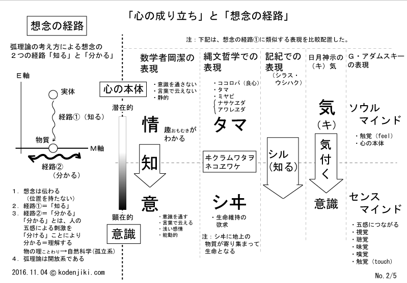 図1
図1
図は2016年11月ですから丁度、全体像である「カミの仕組み」がわかってきた頃の図です。
管理人は若い頃にG・アダムスキーによる「テレパシー」なる本を読みました。
 写真1
写真1
当時、”こんな考え方があるんだ!”という驚きがあり、大変影響を受けた記憶があります。だけれども管理人はアダムスキー原理主義者にはなりませんでした。G・アダムスキーの考えに腑に落ちない点もあったからです。この点は幸いでした。「これはこれ、あれはあれ」という姿勢は現在でも変わりません。
岡潔とヲシテ文献を同時並行で考える内に図1に示したとおりの相関があると気付いたのです。あれこれ考えて2017年と2018年にかけて弧理論を取り巻く全体像(カミの仕組み)と自然科学の問題点のそれぞれについてがだいたいわかってきました。
こういった経緯で岡潔が考えたであろう事について自分なりに考察を続けてきました。
で、本題です。 どうも、管理人の思考方法が岡潔のそれに近いというか、近づいているというか、何と表現してよいかわかりませんけれども、「究極まで(基本的なことを)究極まで簡単化して考える」という方法をとっているようです。
記事を書く際には、よく「数学者岡潔思想研究会」のサイトを利用させていただいているのですけど、先日、岡潔講演録(21)「1971年度京都産業大学講義録第11回」の「【10】 右の内耳」が気になりました。この記事にある「右の内耳に関心を集め続ける」ということの意味を貴方もわからないでしょうし、なぜ右の内耳なのか管理人もわかりません。
岡潔が”関心を集め続ける”ことを「精神統一」と言った言葉で表現したのは誤解を招くと前々回の記事で記した通りです。 実はG・アダムスキーが最も重視したのは「想念観察」でした。よく考えると岡潔が「右の内耳に関心を集め続ける」という動作というか思考方法は想念観察そのものです。 「目はつぶらずに、しかし目に入るものに興味は移らず、問題に関心を集め続ける」、そして『聞こゆるを聞き、見ゆるを聞く』というのは、まぎれもなく想念観察であり、ある科学者の云った「受信の態度」そのものです。道理で管理人のそれと似ているはずです。 ただし、右の内耳に関心を集め続けるのは、岡独自の方法であって一般的ではないようです。
そういえば、FE研究者のI氏から似たことを聞いたことがあります。I氏曰く「右の耳(右肩・右の方向?)にラップ音がある」とのことでした。これは管理人がこれまでの経験について話したことの返答でした。こういうのをラップ音というのをこのとき知りました。
どうも岡潔の述べた言葉は、途轍もなく凝縮されています。平易な言葉であるけど、噛めば噛むほどに深くて味があります。管理人は最近まで岡潔講演録の内のわずか4ページ分ほどを参考に考察を進めてきました。大量にある岡潔のほとんどをまだ読んでいません。それほどに深くて凝縮されています。ネット上の岡潔の著作に関する感想を読んで思うのは、感想のいずれも速読したように見受けられることです。大量に読み込んで簡単に感想を述べています。その感想のいずれもが薄すぎます。岡潔が自らの長い長い時間をかけて考えた結果を「さらり」と述べているので、その深さに気付かないのかも知れません。一気に読み飛ばさず気になる部分だけについてじっくり「興味を集め続け」ては如何でしょう。
そうすれば、現代が如何に奇妙で不自然な状態にあるかわかってくるはずです。過去記事に「近い未来の人たちは、我々の文明のことを(信仰の時代)と呼ぶだろう」と書いた記憶があります。お金は皆が信じているから成り立っています。皆が信じなくなった瞬間に全崩壊します。人類史上、最強最大の信仰です。世界中の宗教は、最強最大の信仰に添える「刺身のつま」でしかありません。 岡潔が当時、人類の危機を云ったのは、深く深く考えた結果です。「間違った思想の洪水」とは何だったのか考えてしまいます。立場上、云えなかったことも多かったと推察します。「【 5】 自然科学の無知」
一つ注意があります。日常生活はとても忙しいです。想念観察は、埋没すると自身を危険に晒します。散歩やウオーキング、入浴や就寝時などが適当ですけれども、街中では事故に遭う危険があります。皆が忙しすぎるため、ムリな面もあります。 一方でどこかの誰かは皆に時間の余裕ができることを嫌っています。だから皆が忙しいとも云えます。皆が自覚のないSheepleのままで居て欲しいのです。また、「小人閑居して不善を為す」とも云います。対して、岡潔の場合は環境があったからこそとも云えますが、同時に岡潔の天才は、「環境からして不善を為さなかった」という自身の努力があったからのようです。『岡潔: 「天才ですか?」 いいえ、努力の人間です』 暇だとつい怠けてしまいます。
追記 ちょっと面白いので掲載します。第一部は実に興味深いです。
動画1
動画2
動画3
追記19/01/12 ほとんどの人が冒頭で示した岡潔の云うことに興味を持てないような気がします。偉大な数学者だから何か凄いことを云っているのだろうと耳を貸すだけです。正直に云うと”己が持つ常識と照らし合わせて”、G・アダムスキーはインチキ臭いです。岡潔と同列に扱うなと云われるかも知れません。管理人は、動画に示した高野誠鮮氏のように一次情報を集められる環境も能力もありません。過去記事に情報は陳腐化すると記したことがあります。一次情報がすべてです。 ですから、管理人の環境下において何が本当なのか見極めることは極めて困難です。鵜呑みになんかできません。自分で考えるしかありません。で、直接の証拠がないならば、G・アダムスキーやダニエル・フライやヲシテ文献などなど惹かれるものから学んで、古今東西のあれこれに”共通”する何かがあれば、それらにはきっと普遍性があるはずだと考えます。岡潔は仏教思想をわかりやすく現代の言葉で解説してくれます。その他の資料とつきあわせて合理的に判断して共通する何かがあればそれは本物だと考えてよいのではと思います。 異星人やUFOが本当かどうかは後から付いてくるのだと思います。きっとそうです。UFOの破片や目撃情報などほとんど価値はありません。むしろどうでもよいことです。UFOや異星人などの話は宇宙の話などではなく、我々個々人の内なる問題なのだと感じます。
その意味で、異星人がG・アダムスキーにコンタクトした理由がわかります。G・アダムスキー:久保田八郎訳になる「空飛ぶ円盤の真相」(高文社)から一部引用します。
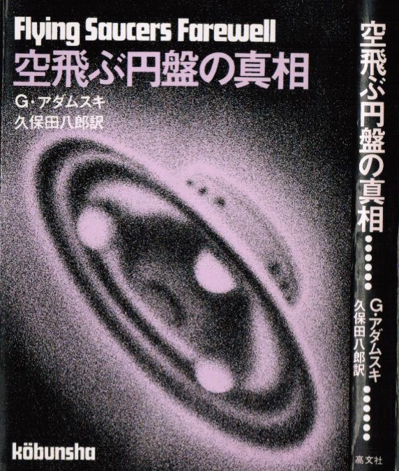 写真2
写真2
さて、この象形文字が私に与えられたおもな理由の一つは、地球人が欲しがっていることを宇宙人が知っていたという〝具体的な証拠〟を与えるためであった。
宇宙の兄弟たちは次の事実を認めている。すなわち地球の古代文明の歴史やその文明の哲学のなかには、彼らの遊星上で知られていて、そこに住む人々によって保たれている歴史や哲学と一致するものがあって、それが例の象形文字のなかに述べられているというのだ。
それで、ずっと以前に私に与えられたあの象形文字の完全な説明をすることは現在でも私にはできないけれども、その文字はおそらく目的を果たしたであろう。宇宙人たちは満足の意を表わしている。
「私」とはG・アダムスキーのことです。象形文字とは、G・アダムスキーが遺したネガフィルムに映っていた宇宙文字と呼ばれるものです。
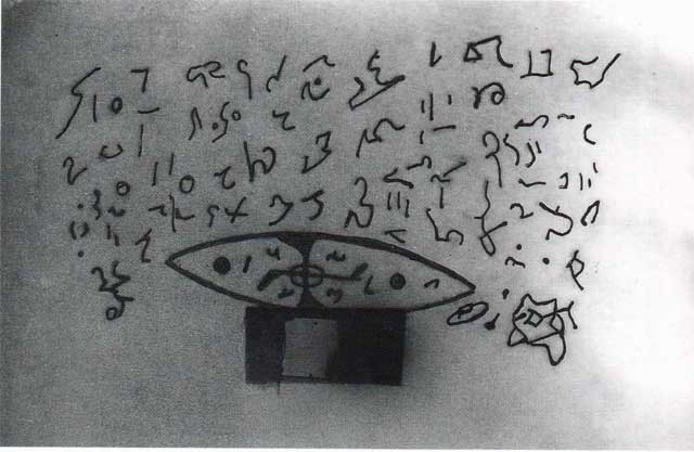 写真3
写真3
2018年7月2日『弧理論 (Ark Theory)の意味するところ → 「異星人の持つ哲学」=「古代縄文人の哲学」』を参照ください。
詰まるところ、”共通の何か”をはっきりさせれば、UFOや異星人のことがわかってくるはずです。彼らの目論見はここにあります。
ブログランキングの応援と広告のクリックをお願いします。


 写真1
写真1 写真2 匙はスプーン、スプーンは匙、「言葉は循環、言葉に物の本質はない」
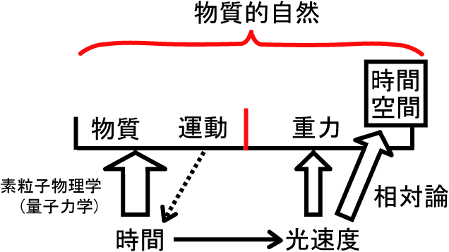 図1
図1 写真1 出典:
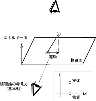 図1
図1 図2
図2 図1
図1 写真1
写真1 写真2
写真2 写真3
写真3 図1 出典:
 写真1
写真1